
Selecting the appropriate speed reducer for your motor system requires careful consideration of multiple technical factors to ensure optimal performance and longevity. Engineers and technicians must evaluate motor specifications, load requirements, and environmental conditions to make informed decisions. The process involves analyzing torque requirements, speed ratios, mounting configurations, and operational parameters. Understanding these critical elements will help you avoid costly mistakes and achieve reliable system performance. Proper speed reducer selection directly impacts equipment efficiency, maintenance costs, and overall system reliability in industrial applications.
Understanding Motor Specifications for Speed Reducer Selection
Motor Power and Torque Characteristics
Motor power rating serves as the foundation for speed reducer selection, as it determines the maximum torque available for transmission. Electric motors produce different torque characteristics depending on their design, with AC motors typically providing constant torque over their operating range. The nameplate power rating indicates the motor's continuous duty capability, but peak torque values may exceed this rating during startup or overload conditions. Engineers must consider both continuous and intermittent torque requirements when sizing a speed reducer to ensure adequate safety margins.
Torque multiplication through a speed reducer increases proportionally with the gear ratio, making it essential to calculate the exact torque requirements at the output shaft. Motor torque curves vary with speed, particularly for variable frequency drive applications where torque may decrease at higher speeds. Understanding these characteristics helps determine whether additional torque capacity is needed in the speed reducer selection. The relationship between motor torque and speed reducer input requirements must be carefully analyzed to prevent overloading or underutilizing the system components.
Speed Range and Operating Characteristics
Motor speed specifications directly influence speed reducer ratio selection, as the output speed must match application requirements. Standard AC motors typically operate at fixed speeds determined by pole count and frequency, while variable speed drives allow for adjustable output speeds. The speed reducer ratio calculation involves dividing input speed by desired output speed, but practical considerations may require adjustments to standard ratio offerings. Speed variations due to load changes, temperature effects, or voltage fluctuations should be considered in the selection process.
Operating speed range affects bearing life, lubrication requirements, and thermal management within the speed reducer housing. High-speed applications may require special bearing arrangements or cooling provisions, while low-speed operations might need enhanced sealing to prevent contamination. The duty cycle and frequency of speed changes also impact component selection, particularly for applications with frequent starts, stops, or reversals. Proper speed reducer selection ensures optimal performance across the entire operating range while maintaining acceptable service life.
Load Analysis and Torque Requirements
Calculating Output Torque Demands
Accurate load analysis forms the cornerstone of proper speed reducer sizing, requiring detailed understanding of application requirements and operating conditions. Static loads represent the basic torque needed to overcome friction and maintain steady-state operation, while dynamic loads include acceleration, deceleration, and shock loading. Engineers must calculate peak torque requirements during startup, as many applications require significantly higher torque to overcome static friction and inertia. The speed reducer must handle these peak loads without damage while providing adequate safety factors for long-term reliability.
Service factors account for application-specific conditions such as shock loading, temperature extremes, duty cycle variations, and environmental contamination. A well-designed speed reducer selection process incorporates these factors to prevent premature failure and ensure reliable operation. Load calculations should include all forces acting on the output shaft, including radial and axial loads that may affect bearing selection and mounting requirements. Proper documentation of load analysis provides valuable information for maintenance planning and troubleshooting.
Dynamic Load Considerations
Dynamic loading conditions significantly impact speed reducer selection, particularly in applications with varying loads or cyclical operations. Inertia matching between the motor and load through the speed reducer affects system response time and energy efficiency. High inertia loads may require larger speed reducer ratings to handle acceleration torques, while low inertia systems might experience instability without proper damping. The speed reducer must accommodate these dynamic effects while maintaining smooth power transmission and acceptable vibration levels.
Shock loading from external sources or sudden load changes requires special consideration in speed reducer selection, as these conditions can cause premature gear wear or catastrophic failure. Impact factors and load distribution patterns help determine the appropriate safety margins and component specifications. Applications with reversing loads or bidirectional operation need speed reducer designs that can handle these challenging conditions without backlash or performance degradation. Understanding dynamic load patterns enables engineers to select speed reducer configurations that provide optimal performance and reliability.
Gear Ratio Selection and Speed Calculations
Determining Optimal Reduction Ratios
Gear ratio selection directly affects system performance, efficiency, and cost, making it a critical decision in speed reducer specification. The ideal ratio provides the required output speed while maximizing torque transmission efficiency and minimizing heat generation. Standard ratio offerings from manufacturers may not exactly match calculated requirements, necessitating selection of the closest available ratio and adjustment of other system parameters. Multiple-stage speed reducer designs allow for greater flexibility in achieving specific ratios while maintaining compact packaging and high efficiency.
Ratio selection impacts backlash characteristics, with higher ratios typically producing increased backlash that may affect positioning accuracy in precision applications. The relationship between gear ratio and efficiency varies with speed reducer design, as higher ratios may increase losses due to additional gear meshes. Engineers must balance ratio requirements with efficiency considerations to optimize overall system performance. Speed reducer ratio selection also affects maintenance requirements, as some ratios may result in more even wear patterns and extended service life.
Speed Matching and System Integration
Proper speed matching ensures optimal power transfer between the motor, speed reducer, and driven load while minimizing energy losses and mechanical stress. The speed reducer serves as the interface between these components, requiring careful consideration of speed relationships and torque characteristics. System integration involves analyzing the complete power train to identify potential resonance frequencies, critical speeds, or other dynamic issues that could affect performance. Speed reducer selection must account for these system-level considerations to ensure trouble-free operation.
Variable speed applications require special attention to speed reducer selection, as the unit must perform efficiently across a wide range of operating speeds. Some speed reducer designs may exhibit reduced efficiency or increased noise at certain speed ranges, requiring careful evaluation of performance curves. The interaction between variable frequency drives and speed reducer characteristics can affect motor current consumption and thermal performance. Proper speed reducer selection for variable speed applications considers these factors to optimize system efficiency and reliability.
Environmental and Mounting Considerations
Environmental Protection Requirements
Environmental conditions significantly influence speed reducer selection, particularly regarding sealing, materials, and protective features. Outdoor installations require weather-resistant housings and enhanced sealing systems to prevent water and contaminant ingress. Temperature extremes affect lubricant selection, thermal expansion, and material compatibility within the speed reducer assembly. Corrosive environments may necessitate special coatings, stainless steel components, or alternative materials to ensure long-term reliability and performance.
Dust and particle contamination can severely impact speed reducer performance, requiring appropriate ingress protection ratings and filtration systems. The speed reducer housing design must prevent contamination while allowing for thermal expansion and pressure equalization. Vibration and shock conditions in the installation environment affect mounting requirements and internal component specifications. Environmental assessment ensures that the selected speed reducer can withstand operating conditions throughout its intended service life without performance degradation.
Mounting Configuration and Space Constraints
Physical mounting requirements often dictate speed reducer selection, as space limitations and configuration constraints may eliminate certain options. Standard mounting positions include foot-mounted, flange-mounted, and shaft-mounted configurations, each offering different advantages for specific applications. The mounting arrangement affects heat dissipation, accessibility for maintenance, and structural loading on support systems. Speed reducer selection must consider these factors to ensure proper installation and long-term reliability.
Space constraints may require compact speed reducer designs or alternative mounting arrangements that affect performance characteristics. Hollow shaft configurations allow for direct mounting on driven equipment shafts, eliminating coupling requirements and reducing overall system length. The mounting interface must accommodate thermal expansion, vibration, and misalignment while maintaining precise positioning and load transfer. Proper mounting selection ensures optimal speed reducer performance while meeting installation requirements and maintenance accessibility needs.
Efficiency and Performance Optimization
Maximizing Power Transmission Efficiency
Speed reducer efficiency directly impacts overall system energy consumption and operating costs, making it an important selection criterion for many applications. High-efficiency designs minimize power losses through optimized gear geometries, premium materials, and precise manufacturing tolerances. The relationship between efficiency and load varies with speed reducer design, as some units maintain high efficiency across a wide load range while others may exhibit reduced performance at partial loads. Understanding these characteristics helps engineers select speed reducer configurations that optimize energy usage.
Lubrication systems significantly affect speed reducer efficiency, with proper lubricant selection and maintenance essential for optimal performance. Synthetic lubricants may offer improved efficiency and extended service intervals compared to conventional oils, but at higher initial costs. Temperature management through adequate cooling and heat dissipation maintains lubricant properties and prevents efficiency degradation. Speed reducer selection should consider long-term efficiency trends and maintenance requirements to ensure sustained performance throughout the service life.
Performance Monitoring and Maintenance
Modern speed reducer designs incorporate features that facilitate performance monitoring and predictive maintenance programs. Vibration monitoring, temperature sensors, and oil analysis capabilities help identify potential issues before they result in catastrophic failure. The speed reducer selection process should consider maintenance accessibility, component replaceability, and monitoring capability requirements. Systems with critical uptime requirements may benefit from speed reducer designs that support condition-based maintenance strategies.
Maintenance requirements vary significantly between different speed reducer types and applications, affecting total cost of ownership calculations. Sealed-for-life units minimize maintenance but may have limited service life, while serviceable designs allow for extended operation with proper care. The selection process must balance initial cost, maintenance requirements, and expected service life to optimize total system economics. Regular maintenance scheduling and procedures should be established during the speed reducer selection phase to ensure optimal performance throughout the operating life.
FAQ
What factors determine the required service factor for a speed reducer
Service factors depend on application conditions including shock loading, temperature extremes, duty cycle variations, and environmental contamination. Typical service factors range from 1.0 for uniform loads in controlled environments to 2.5 or higher for severe shock loading conditions. The service factor multiplies the calculated torque requirement to provide adequate safety margin and ensure reliable operation throughout the expected service life.
How does ambient temperature affect speed reducer selection
Temperature extremes affect lubricant viscosity, thermal expansion, and material properties within the speed reducer assembly. High temperatures may require synthetic lubricants, enhanced cooling, or reduced load ratings, while low temperatures can increase lubricant viscosity and starting torque requirements. Environmental temperature ranges should be considered during selection to ensure proper operation and prevent premature component failure.
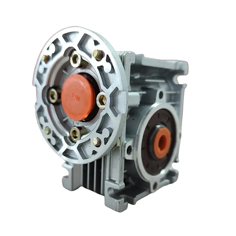
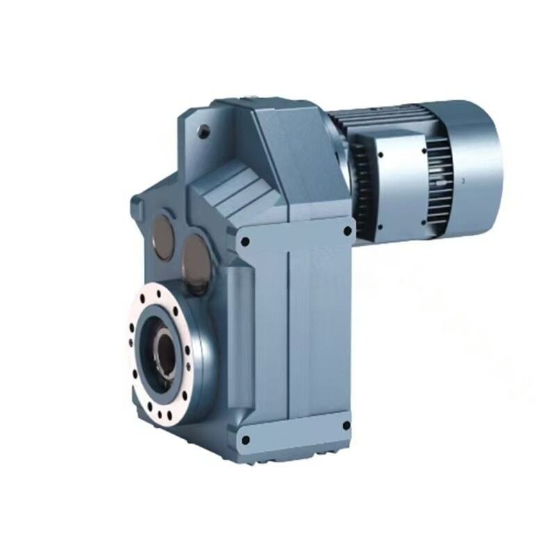
What is the difference between helical and worm gear speed reducers
Helical gear speed reducers offer higher efficiency, typically 94-98%, and can handle higher speeds and loads compared to worm gear units. Worm gear speed reducers provide higher reduction ratios in a single stage, inherent self-locking capability, and quieter operation but with lower efficiency, typically 50-90%. The choice depends on application requirements for efficiency, reduction ratio, self-locking, and space constraints.
How do you calculate the required output torque for a speed reducer application
Output torque calculation involves determining the torque needed to overcome load resistance, including friction, acceleration, and gravity effects. The formula includes load inertia, acceleration requirements, friction coefficients, and safety factors. For rotating loads, multiply the load torque by the service factor, while linear applications require force calculations converted to equivalent torque values through pulley or sprocket diameters.