Industrial machinery relies heavily on precise power transmission systems to achieve optimal performance and efficiency. A gear reducer serves as a critical mechanical component that transforms high-speed, low-torque input into low-speed, high-torque output, enabling machines to operate with enhanced control and power delivery. Understanding how these devices function and their impact on mechanical systems is essential for engineers, manufacturers, and equipment operators seeking to maximize productivity while minimizing energy consumption and operational costs.
The fundamental principle behind gear reducer operation involves mechanical advantage through gear ratio manipulation. When an electric motor or other prime mover generates rotational force, this energy often needs modification to match specific application requirements. Modern manufacturing processes demand precise torque control and speed regulation, making the gear reducer an indispensable element in countless industrial applications across diverse sectors including automotive, aerospace, food processing, and heavy machinery.
Understanding Gear Reducer Fundamentals
Mechanical Principles of Torque Multiplication
The core function of a gear reducer centers on the relationship between speed and torque in rotating mechanical systems. According to the conservation of energy principle, when rotational speed decreases through gear reduction, torque increases proportionally, assuming minimal energy losses due to friction and mechanical inefficiencies. This torque multiplication occurs through the interaction of gears with different diameters and tooth counts, where the input gear drives larger output gears to achieve the desired speed-torque conversion.
The gear ratio determines the exact relationship between input and output characteristics. For example, a gear reducer with a 10:1 ratio will reduce input speed by a factor of ten while increasing torque by approximately the same factor. This mathematical relationship allows engineers to calculate precise output specifications based on input parameters and system requirements. The gear reducer effectively transforms electrical motor characteristics to match mechanical load demands, ensuring optimal power transfer and system efficiency.
Advanced gear reducer designs incorporate multiple gear stages to achieve higher reduction ratios while maintaining compact form factors. Each stage contributes to the overall reduction ratio through multiplicative effects, allowing manufacturers to create systems capable of dramatic speed reductions and substantial torque increases. These multi-stage configurations enable applications requiring extremely high torque output from relatively compact motor arrangements.
Types and Configurations of Gear Reducers
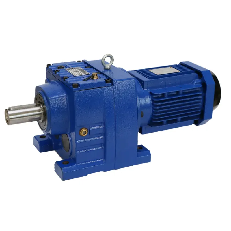
Various gear reducer configurations serve different industrial applications based on specific performance requirements, space constraints, and operational conditions. Helical gear reducers provide smooth, quiet operation with high efficiency ratings, making them suitable for precision applications where noise reduction and consistent performance are critical. The helical gear design distributes loads across multiple teeth simultaneously, reducing wear and extending operational lifespan compared to straight-cut gear alternatives.
Planetary gear reducer systems offer exceptional torque density and compact packaging through their unique configuration of central sun gears, orbital planet gears, and outer ring gears. This arrangement distributes loads across multiple gear meshes simultaneously, enabling higher torque capacity within smaller enclosures. Planetary designs also provide multiple output options and can achieve high reduction ratios in single-stage configurations, making them ideal for space-constrained applications.
Worm gear reducer configurations excel in applications requiring high reduction ratios and self-locking capabilities. The perpendicular arrangement of worm and wheel gears enables compact designs with excellent backdrive resistance, making them suitable for lifting applications and positioning systems where load holding is essential. However, worm gear systems typically exhibit lower efficiency compared to parallel-shaft arrangements due to increased sliding friction between gear surfaces.
Efficiency Enhancement Through Gear Reducer Implementation
Power Transmission Optimization
Implementing a gear reducer in mechanical systems significantly improves overall power transmission efficiency by matching motor characteristics to load requirements. Electric motors typically operate most efficiently within specific speed ranges, often higher than optimal speeds for many mechanical applications. The gear reducer bridges this gap by allowing motors to operate within their peak efficiency zones while delivering appropriate output characteristics for downstream equipment.
Energy losses in direct-drive systems often result from motors operating outside their optimal performance curves, leading to increased electrical consumption and reduced overall system efficiency. A properly selected gear reducer enables motor operation at peak efficiency points while providing the necessary speed and torque characteristics for specific applications. This optimization can result in energy savings of 10-30% compared to oversized direct-drive alternatives or variable frequency drive solutions in constant-load applications.
Modern gear reducer designs incorporate advanced materials and manufacturing techniques to minimize internal losses through improved gear tooth profiles, precision bearings, and optimized lubrication systems. High-quality gear reducers can achieve efficiency ratings exceeding 95% in single-stage configurations and 85-90% in multi-stage arrangements, ensuring minimal energy waste during power transmission processes.
System Performance and Control Benefits
Beyond efficiency improvements, gear reducer integration enhances system control capabilities and operational precision. Reduced output speeds enable finer positioning control and smoother operation in applications requiring precise motion control or positioning accuracy. The increased torque multiplication also provides better load handling capabilities and improved starting torque characteristics for high-inertia loads or applications with significant breakaway torque requirements.
The mechanical advantage provided by gear reducer systems reduces stress on upstream components including motors, drives, and control systems. Lower motor currents required for equivalent output torque result in reduced electrical system demands, smaller wire sizing requirements, and decreased thermal stress on motor windings. This reduction in component stress typically translates to extended equipment lifespan and reduced maintenance requirements across the entire drive system.
Gear reducer implementation also improves system response characteristics by providing mechanical dampening effects that reduce oscillations and vibrations in drive systems. The added rotational inertia and gear mesh compliance help smooth out torque pulsations and reduce torsional vibrations that can cause premature wear or operational issues in sensitive applications.
Industrial Applications and Performance Impact
Manufacturing and Production Equipment
Manufacturing environments extensively utilize gear reducer technology to optimize production equipment performance and ensure consistent product quality. Conveyor systems rely on gear reducers to provide appropriate belt speeds while maintaining sufficient torque for material handling operations. The precise speed control enabled by gear reducer systems ensures consistent material flow rates and prevents product damage due to excessive acceleration or deceleration forces.
Machining centers and CNC equipment incorporate gear reducer systems in spindle drives, feed mechanisms, and tooling systems to achieve the precise speed and torque characteristics required for accurate material removal and surface finishing. The torque multiplication capabilities of gear reducers enable heavy cutting operations while maintaining spindle speeds within acceptable ranges for tool life optimization and surface quality requirements.
Assembly line equipment utilizes gear reducer technology to synchronize multiple operations and ensure consistent cycle times across production processes. The reliable speed reduction and torque amplification provided by quality gear reducer systems enable automated assembly equipment to handle varying part weights and assembly forces while maintaining precise positioning and timing requirements essential for high-volume production operations.
Heavy Industry and Construction Applications
Construction and mining equipment rely heavily on gear reducer systems to provide the extreme torque requirements necessary for earth-moving, material handling, and extraction operations. Excavators, bulldozers, and crane systems utilize multiple gear reducer configurations to convert high-speed hydraulic motor output into the low-speed, high-torque characteristics required for effective operation under severe loading conditions.
Wind turbine installations represent a significant application area where gear reducer technology enables efficient energy conversion from variable wind speeds to consistent generator input speeds. The gear reducer systems in wind turbines must handle extreme environmental conditions while providing reliable speed conversion and torque transmission across wide operating ranges. Modern wind turbine gear reducers incorporate advanced materials and design features to ensure 20-year operational lifespans under demanding conditions.
Steel mills and heavy processing facilities utilize massive gear reducer systems to drive rolling mills, crushers, and material handling equipment. These applications demand extreme torque capacity and reliability under continuous operation with high shock loads and varying operating conditions. The gear reducer systems in these applications often incorporate multiple parallel paths and redundant components to ensure operational continuity and prevent costly production interruptions.
Selection and Sizing Considerations
Performance Requirements and Specifications
Proper gear reducer selection requires careful analysis of application requirements including torque capacity, speed ratios, efficiency targets, and environmental operating conditions. Load calculations must account for both steady-state operational requirements and dynamic loading conditions including startup torque, shock loads, and cyclic variations. Service factor applications help ensure adequate safety margins for unexpected loading conditions and extended operational life under varying duty cycles.
Environmental considerations significantly impact gear reducer selection and configuration requirements. Temperature extremes, moisture exposure, chemical compatibility, and contamination resistance all influence material selection, sealing requirements, and lubrication system design. Industrial applications often require specialized gear reducer configurations with enhanced protection ratings, corrosion-resistant materials, or explosion-proof enclosures for hazardous environment operation.
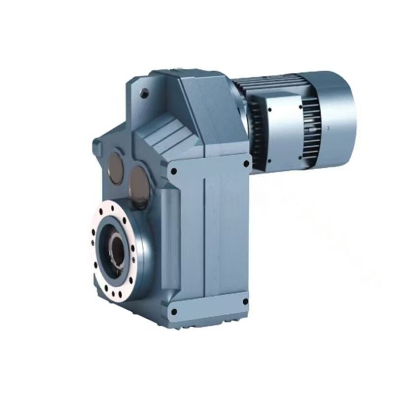
Mounting configurations and space constraints frequently drive gear reducer selection decisions in retrofit applications or equipment with limited installation space. Hollow shaft outputs, various mounting orientations, and integrated motor combinations provide flexibility for challenging installation requirements while maintaining performance specifications and operational reliability.
Maintenance and Operational Optimization
Effective gear reducer maintenance programs significantly impact operational efficiency and equipment lifespan. Regular lubrication monitoring, vibration analysis, and thermal imaging help identify potential issues before they result in catastrophic failures or extended downtime. Predictive maintenance techniques enable optimization of maintenance intervals while ensuring reliable operation and maximizing return on equipment investments.
Lubrication system maintenance represents a critical aspect of gear reducer care, as proper lubricant selection and change intervals directly impact efficiency, wear rates, and operational temperature. Synthetic lubricants often provide superior performance characteristics including extended change intervals, improved low-temperature operation, and better thermal stability compared to conventional petroleum-based alternatives.
Performance monitoring systems increasingly incorporate advanced sensing technologies to provide real-time feedback on gear reducer operating conditions including temperature, vibration, lubricant condition, and load characteristics. These monitoring capabilities enable proactive maintenance scheduling and operational optimization while providing valuable data for improving system design and performance in future applications.
FAQ
How much torque increase can I expect from a gear reducer?
The torque increase from a gear reducer directly corresponds to its reduction ratio, minus efficiency losses. For example, a 20:1 gear reducer will theoretically increase torque by a factor of 20, but accounting for typical efficiency rates of 90-95%, the actual torque multiplication will be approximately 18-19 times the input torque. Higher reduction ratios provide greater torque multiplication but may involve multiple stages that can reduce overall efficiency.
What factors affect gear reducer efficiency in industrial applications?
Several factors influence gear reducer efficiency including gear quality and manufacturing precision, lubrication type and condition, operating temperature, load characteristics, and speed ranges. High-quality gear reducers with precision-manufactured components and proper lubrication typically achieve 90-98% efficiency in single-stage configurations. Multi-stage units may have slightly lower efficiency due to additional gear meshes and bearing losses.
How do I determine the correct gear reducer size for my application?
Proper gear reducer sizing requires calculating the required output torque, desired speed reduction ratio, and applying appropriate service factors for your specific application. Consider peak loads, duty cycles, environmental conditions, and mounting requirements when making selections. Consulting with gear reducer manufacturers or qualified engineers helps ensure optimal sizing for reliable, long-term operation while avoiding over-specification that increases costs unnecessarily.
What maintenance is required to keep a gear reducer operating efficiently?
Regular gear reducer maintenance includes periodic lubricant changes based on manufacturer recommendations, typically every 2,500-5,000 operating hours depending on conditions. Monitor operating temperatures, vibration levels, and noise characteristics for signs of wear or impending issues. Inspect seals, breathers, and mounting hardware regularly, and maintain proper lubricant levels to ensure optimal performance and maximum operational life.