
 EN
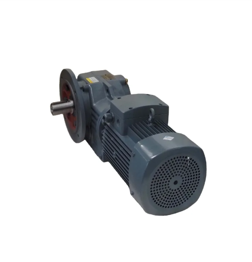
Core Performance Factors in Speed Reducer Selection
Determining Torque Requirements for Load Capacity
Getting the right torque specs matters a lot when picking out a speed reducer because if there isn't enough torque, equipment just won't perform well or might even fail completely. Torque basically refers to how much rotational force comes from gears working together. When someone gets this part wrong, machines tend to struggle or break down sooner than expected. For proper matching, looking at both what stays constant (static loads) and what changes during operation (dynamic loads) makes all the difference. The math behind figuring out load torque usually requires some formulas that take force measurements (in Newtons) and distances from pivot points (measured in meters). Industry standards offer helpful benchmarks for these calculations so engineers don't end up with reducers that sit idle most of the time or get pushed beyond their limits. Still worth noting though, no formula covers every situation perfectly, so experience plays a big role here too.
Calculating Optimal Speed Reduction Ratio
Getting the right speed reduction ratio sorted out makes all the difference when it comes to making equipment work better and lasting longer. Basically, what we're talking about here is comparing how fast something goes in versus how fast it comes out, which has a direct impact on how well motors perform and how machines run overall. Most folks figure out the best ratio by looking at what RPM the motor is rated for compared to what they actually want coming out of the system. When people get this wrong, bad things happen - parts start wearing down faster than normal, things tend to overheat, and efficiency just drops off completely. To avoid headaches like this, always start with what kind of output speed the machine needs to function properly. Don't forget to factor in how much weight or force the system will be handling too. Following this method means every part of the whole setup ends up working exactly where it performs best, which ultimately saves money and keeps operations running smoothly day after day.
Balancing RPM and Torque Output Efficiency
Getting the right mix between RPMs (those revolutions per minute numbers) and how much torque something produces really matters when it comes to making systems work well. RPM basically tells us how fast parts are spinning around inside whatever machine we're talking about. Push those RPMs too high though, and machines start to feel the strain. Components get worn out faster, things stop working as they should. When RPM and torque levels match up properly, energy gets used where it needs to go instead of wasting itself on stressed out parts. Small changes in RPM rates actually make big differences over time both in how much power gets consumed and how long equipment lasts before breaking down. Manufacturers who focus on getting this balance just right tend to see their machines running better overall. They experience fewer breakdowns, less noise during operation, and generally spend less money replacing parts because everything wears down at a slower rate.
Understanding these core performance factorsâtorque requirements, speed reduction ratio, and the balance between RPM and torque output efficiencyâprovides a framework for informed speed reducer selection, enhancing both productivity and reliability in industrial applications.
Types of Gear Reducers and Application-Specific Considerations
Planetary Gearboxes for High Torque Density
Planetary gearboxes stand out because they take up less space while still delivering impressive torque. These systems work with three main components: sun gears, planet gears, and ring gears. When these parts mesh together, they spread out the workload across multiple points, which means more power gets transferred through a much smaller package. That's why engineers love using them wherever there's limited room but lots of power needs, especially in areas like robotics and aircraft manufacturing. Take industrial robots for instance. Space matters a lot here since every millimeter counts, yet these machines need serious strength to handle heavy loads. Planetary gearboxes let designers pack all that power into tight spaces without compromising on what the robot can actually do. What really sets them apart though is this amazing balance between weight and torque output. A good torque-to-weight ratio means manufacturers can build lighter equipment that still packs a punch when it comes to force generation.
Worm Gear Reducers for Compact, Non-Reversible Systems
Worm gear reducers stand out because they're simple, take up little space, and work well with big reduction ratios. That makes these gears ideal for places where there's not much room and quiet operation matters, think conveyor belts or elevator mechanisms. What's interesting about them is their one-way action. Once something gets lifted or moved, it stays put without slipping backward. This becomes really important safety-wise in things like cranes or hoists where accidental movement could cause problems. The downside? While their basic design helps keep everything small and allows for those high reductions, the gears start losing efficiency when pushed too far. So engineers need to weigh what's needed for each job before deciding if worm gears are the right choice for balancing power transmission against energy losses.
Bevel and Parallel-Shaft Configurations
Choosing between bevel and parallel-shaft setups really comes down to what works best for the job at hand. Bevel gears stand out because they can actually redirect motion when shafts cross paths, which makes them pretty handy wherever direction changes matter. We see this all over the place in cars and big industrial equipment. On the flip side, parallel-shaft arrangements keep things simple since the shafts run alongside each other. They transmit torque efficiently without messing with the direction of movement, so they work great for basic power transfer needs. Both options have their own sweet spots depending on how they're installed and what kind of efficiency matters most. Getting this straight helps engineers pick the right gear solution for different manufacturing environments.
Mechanical Configuration and Installation Requirements
Coaxial vs. Orthogonal Shaft Orientations
Choosing the right speed reducer means knowing whether to go with coaxial or orthogonal shaft arrangements, which makes all the difference when it comes to how things fit together in machinery. Coaxial shafts line up input and output on the same axis, creating tighter packages that save precious floor space. This setup works wonders for tight spaces like automated assembly lines or miniaturized robotic arms where every inch counts. Orthogonal shafts take a different approach with their 90 degree angle configuration. These tend to handle heavier loads better while keeping vibrations under control, making them ideal for heavy duty applications like belt conveyors in manufacturing plants or big agri-machinery. The choice really depends on what matters most for each project space constraints versus power transmission needs. Engineers need to balance these factors against actual operating conditions rather than just following textbook formulas.
Adapting Mounting Interfaces to Existing Systems
Getting speed reducers to work well with what's already there matters a lot when installing them properly. The way mounting points fit together with existing machinery needs careful thought. When things aren't adapted correctly, problems pop up all the time. We've seen misalignments happen, parts wearing down faster than they should, and sometimes whole systems just stop working. That usually means going back and doing extra integration work later on. Most setups use standard mounting options like flange connections, different types of shafts, or specific bolt hole arrangements. These need to match up pretty exactly if everything is going to function smoothly together. Good practice here means checking out the mechanical details really thoroughly before installation starts. Flexibility kits come in handy too, those special adapters that bridge gaps between old and new components. They make the whole process easier to manage and cut down on alignment issues during setup.
Space Constraints and Alignment Precision
When it comes to mechanical systems, both space limitations and how accurately parts line up play a big role in how well they work over time. Installers need to make sure there's enough room for the reducer plus all its supporting components because when things get too cramped, heat builds up and performance drops off. Getting the alignment right matters just as much though. If parts aren't properly aligned, they'll wear out faster, which means more breakdowns and higher repair bills down the road. Most industry standards recommend keeping alignment errors under 0.1 mm in tough industrial settings where equipment runs nonstop day after day. This level of care pays off in the long run with better overall system performance and fewer unexpected shutdowns that disrupt production schedules.
Environmental and Operational Longevity Factors
Duty Cycle Demands and Shock Load Resistance
When picking out durable speed reducers, duty cycles should be at the top of the checklist. Basically, duty cycles measure how much time a machine runs compared to its entire work period, which directly affects how fast components break down. Machines that run nonstop need speed reducers built for constant operation without overheating or failing. Then there's the issue of shock loads those sudden impacts when something hits the system unexpectedly. These kinds of forces really test if a reducer can handle rough treatment. Getting one that stands up to shock loads makes all the difference between regular maintenance and expensive breakdowns down the road. Standards like ISO 6336 give manufacturers some benchmarks for gear performance across different duty levels, showing clearly which models handle stress better than others in real world conditions.
Temperature Extremes and Contaminant Protection
Extreme temperatures really take a toll on how well lubricants work and how long components last in speed reducers. When things get too hot, the oil starts breaking down and loses its ability to keep gears from rubbing against each other and wearing out. Cold weather presents different problems too. Lubricants thicken when temperatures drop, which can actually stop gears from moving properly. Dust and dirt are another major concern for these systems. That's why good quality seals matter so much they act as barriers against all sorts of nasty stuff getting inside where it doesn't belong. Studies published in various mechanical engineering publications highlight just how critical proper temperature handling and protection from outside elements are for keeping speed reducers running reliably even under tough operating conditions.
Maintenance Accessibility and Service Life
How easy it is to maintain speed reducers plays a major role in how long they last before needing replacement. When manufacturers build these systems with parts that are simple to access for regular inspections and component swaps, the whole system runs better and breakdowns happen less often. The day-to-day stuff matters too – checking oil levels regularly, making sure everything stays properly aligned during operation, all these things keep the reducer running smoothly year after year. Industry experience shows that when companies stick to their maintenance schedules, they typically get around 20% more life out of their equipment because problems get caught early on rather than waiting until something fails completely. Good design that makes maintenance straightforward means operators don't have to tear apart entire assemblies just for routine checks, saving both time and money in the long run while keeping production lines moving without interruption.
FAQ
What is a speed reducer and why is it important?
A speed reducer is a mechanical device used to reduce the speed of a motor while increasing its torque output. It is essential for applications requiring specific speed and power levels, as it helps optimize equipment performance and longevity.
How do I calculate the torque requirements for my speed reducer?
Torque calculation involves assessing both static and dynamic loads in your application. You use the formula: Torque (Nm) = Force (N) x Distance from the pivot (m), factoring in industry standards to ensure efficiency and performance.
What factors affect the selection of a speed reduction ratio?
Factors include the motor's rated RPM, desired output RPM, load characteristics, and operational speed. Choosing the correct ratio ensures optimal performance without excessive wear or overheating.
Why is balancing RPM and torque efficiency crucial for machinery?
Balancing RPM and torque is critical to prevent unnecessary stress on components, ensuring energy is converted efficiently. It enhances machinery operation, reduces wear, and extends service life.
What are the primary types of gear reducers?
Primary types include planetary gearboxes, worm gear reducers, bevel, and parallel-shaft configurations, each suited to specific applications based on space, torque, and motion requirements.