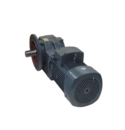
Core Performance Factors in Speed Reducer Selection
Determining Torque Requirements for Load Capacity
Accurately assessing torque requirements is crucial when selecting a speed reducer since insufficient torque can result in equipment underperformance or failure. Torque is the rotational force a gear system exerts, and getting this wrong can severely impact the machinery's effectiveness. To ensure an appropriate match, one must consider both static and dynamic loads of an application. Calculating load torque often involves specific formulas, taking the force (in Newtons) and the distance from the pivot point (in meters) into account. Standards and guidelines in the industry provide reference points to help with these calculations, ensuring the speed reducer is neither underused nor overburdened.
Calculating Optimal Speed Reduction Ratio
Selecting the correct speed reduction ratio is pivotal for boosting equipment efficiency and prolonging its lifespan. The speed reduction ratio compares the input speed to the output speed, directly affecting motor performance and machinery operation. A typical formula for determining the optimal ratio involves considering the motor's rated RPM and the desired output RPM. An incorrect ratio can lead to issues such as excessive wear, overheating, or reduced efficiency. To prevent these problems, the desired operational output speed should guide ratio calculations, also keeping the application's load characteristics in mind. This approach ensures that each component within the system operates at its most effective capacity.
Balancing RPM and Torque Output Efficiency
A harmonious balance between RPM (revolutions per minute) and torque output efficiency is essential for the optimized performance of any system. RPM refers to the rotational speed of a part within the system, and excessive RPMs can strain machinery, leading to inefficiencies or possible malfunctions. The balance between RPM and torque ensures energy is converted without unnecessary stress on the components. Variations in RPM can directly impact energy consumption and system durability, so finding the right balance is crucial. Numerous studies have shown that by optimizing this balance, machinery runs smoother, quieter, and more efficiently, reducing wear and extending service life.
Understanding these core performance factors—torque requirements, speed reduction ratio, and the balance between RPM and torque output efficiency—provides a framework for informed speed reducer selection, enhancing both productivity and reliability in industrial applications.
Types of Gear Reducers and Application-Specific Considerations
Planetary Gearboxes for High Torque Density
Planetary gearboxes are renowned for their compact design and exceptional torque density. By utilizing sun gears, planet gears, and ring gears, planetary gearboxes can distribute load efficiently, resulting in higher torque transfer within a smaller footprint. This makes them ideal for applications requiring both space-saving and high-power output, such as in robotics and aerospace sectors. For example, in the field of robotics, where precision and compactness are crucial, planetary gearboxes allow for streamlined designs without sacrificing performance. The torque-to-weight ratio is one of the key performance metrics that highlights their effectiveness, offering a compact solution where torque density is a critical requirement.
Worm Gear Reducers for Compact, Non-Reversible Systems
Worm gear reducers are characterized by their simplicity, compactness, and ability to handle large reduction ratios, making them suitable for applications that demand minimal space and noise, such as conveyor systems and elevators. Their non-reversible nature means that once a load is applied, it cannot be reversed, which is especially useful in applications needing a safety feature to prevent back driving, such as in lifting machines. Despite their simplistic design favoring compactness and high reduction capability, efficiency can decrease at extreme reduction ratios. This trade-off between reduction capability and energy efficiency must be carefully considered depending on the application.
Bevel and Parallel-Shaft Configurations
When selecting between bevel and parallel-shaft configurations, it's essential to consider their unique design attributes and application suitability. Bevel gears, known for their ability to change the direction of motion through intersecting shafts, are incredibly useful in situations requiring directional shifts, often seen in automotive and heavy machinery industries. In contrast, parallel-shaft configurations, characterized by parallel shaft alignment, provide efficient torque transmission without altering motion directions, making them ideal for straightforward torque transfer. Each type, influenced by installation angles and designed for specific operational efficiencies, brings unique advantages, and understanding these can enhance performance in industry-specific contexts.
Mechanical Configuration and Installation Requirements
Coaxial vs. Orthogonal Shaft Orientations
When selecting a speed reducer, understanding the differences between coaxial and orthogonal shaft orientations is crucial for optimizing installation and layout. Coaxial shafts, where input and output shafts are aligned along the same axis, offer compact designs that maximize space efficiency. This orientation is particularly beneficial in applications where space is limited, such as in compact machinery and small robotics systems. On the other hand, orthogonal shafts, with a 90-degree angle arrangement, excel in scenarios requiring more robust torque handling and minimal vibration, such as conveyor belts and large industrial machinery. Each orientation affects space utilization and mechanical efficiency, demanding careful consideration of the engineering principles and design objectives specific to the application at hand.
Adapting Mounting Interfaces to Existing Systems
Ensuring compatibility with existing systems is another essential factor in the successful installation of speed reducers. This involves considering how the mounting interfaces connect and align with current equipment. Improper adaptation could lead to performance issues, such as misalignment, increased wear, or even operational failures, often necessitating additional systems integration. Common mounting interfaces include flanges, shafts, and bolt patterns that must be precisely adapted to maintain system compatibility. Adopting best practices for adaptation includes thorough mechanical assessments and using flexibility kits, which can help align new components with existing systems, reducing installation complexity and risk of misalignment.
Space Constraints and Alignment Precision
Space constraints and alignment precision are critical for ensuring the operational efficiency and longevity of mechanical systems. Any installation must factor in available space to accommodate the reducer and associated components, as overcrowded setups can lead to overheating and reduced performance. Ensuring precise alignment during installation is equally crucial, as misalignment can accelerate wear and tear, compromising reliability and increasing maintenance costs. Guidelines suggest maintaining an alignment precision within specified tolerances—often less than 0.1 mm for demanding industrial applications—to reduce friction and enhance component lifespan. Balancing these factors correctly can lead to substantial long-term benefits, including improved efficiency and reduced downtime.
Environmental and Operational Longevity Factors
Duty Cycle Demands and Shock Load Resistance
Duty cycles are a vital consideration in the selection of robust speed reducers. They refer to the ratio of operating time to the total cycle time, influencing the wear and tear exerted on the machinery. Systems operating under demanding duty cycles require speed reducers that can withstand continuous usage. Shock load conditions, characterized by sudden force applications, challenge system resilience. Selecting a speed reducer with high shock load resistance is crucial to prevent mechanical failures and prolong the lifespan of equipment. Industry standards, such as ISO 6336, offer guidelines on how gears perform under varying duty cycles, highlighting the differences in stress-handling capabilities among different models.
Temperature Extremes and Contaminant Protection
Temperature extremes can significantly affect lubricant effectiveness and component durability in speed reducers. High temperatures may cause lubricants to degrade, reducing their ability to minimize friction and protect gear surfaces. Conversely, low temperatures may increase lubricant viscosity, potentially hindering optimal gear movement. Additionally, environments rife with contaminants necessitate gear reducers equipped with sturdy seals and enclosures to prevent the ingress of dust or moisture. Research in mechanical engineering journals, such as Mechanical Systems and Signal Processing, underscores the importance of temperature resilience and contaminant protection in prolonging the functionality and reliability of speed reducers in harsh conditions.
Maintenance Accessibility and Service Life
Ease of maintenance is a pivotal factor in prolonging the service life of speed reducers. Systems designed with accessibility for routine checks and part replacements ensure smoother performance and reduce the risk of unexpected downtime. Regular maintenance practices, including lubrication checks and alignment inspections, greatly enhance the operational efficiency and reliability of speed reducers. Statistics suggest that consistent maintenance can increase service life by up to 20% due to timely problem detection and resolution. Incorporating accessible design for upkeep ensures that systems can sustain high performance levels over extended periods, avoiding costly repairs and replacements.
FAQ
What is a speed reducer and why is it important?
A speed reducer is a mechanical device used to reduce the speed of a motor while increasing its torque output. It is essential for applications requiring specific speed and power levels, as it helps optimize equipment performance and longevity.
How do I calculate the torque requirements for my speed reducer?
Torque calculation involves assessing both static and dynamic loads in your application. You use the formula: Torque (Nm) = Force (N) x Distance from the pivot (m), factoring in industry standards to ensure efficiency and performance.
What factors affect the selection of a speed reduction ratio?
Factors include the motor's rated RPM, desired output RPM, load characteristics, and operational speed. Choosing the correct ratio ensures optimal performance without excessive wear or overheating.
Why is balancing RPM and torque efficiency crucial for machinery?
Balancing RPM and torque is critical to prevent unnecessary stress on components, ensuring energy is converted efficiently. It enhances machinery operation, reduces wear, and extends service life.
What are the primary types of gear reducers?
Primary types include planetary gearboxes, worm gear reducers, bevel, and parallel-shaft configurations, each suited to specific applications based on space, torque, and motion requirements.

