
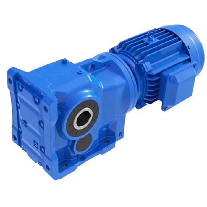
Matching a speed reducer to your existing motor specifications requires careful analysis of power requirements, torque characteristics, and operational parameters. Industrial applications demand precise coordination between motor output and reducer input to ensure optimal performance, longevity, and efficiency. Understanding the fundamental relationship between motor power and speed reducer capabilities forms the foundation for successful mechanical power transmission systems.
The process begins with comprehensive motor documentation review, including nameplate specifications, power curves, and operational history. Motor manufacturers provide detailed specifications that serve as the baseline for speed reducer selection. These specifications include rated power output, operating speed ranges, torque characteristics, and thermal limitations that directly influence reducer compatibility decisions.
Power transmission efficiency depends on accurate matching between motor capabilities and speed reducer design parameters. Mismatched systems often result in premature component failure, reduced operational efficiency, and increased maintenance costs. Professional engineers emphasize the importance of thorough analysis before implementing any speed reducer solution in existing mechanical systems.
Motor Power Analysis and Documentation
Nameplate Data Interpretation
Motor nameplate information provides essential data for speed reducer selection, including rated horsepower, full-load amperage, operating voltage, and frequency specifications. These parameters establish the baseline power characteristics that must be accommodated by the selected speed reducer. Accurate interpretation of nameplate data prevents oversizing or undersizing issues that commonly plague industrial installations.
Full-load torque calculations derive from nameplate power and speed ratings, providing critical input for speed reducer sizing. Motor manufacturers typically specify continuous duty ratings, but peak torque capabilities may exceed nameplate values during startup or load variations. Understanding these dynamic characteristics ensures proper speed reducer selection for demanding applications.
Operating environment factors also influence motor performance characteristics, including ambient temperature, altitude, and duty cycle requirements. These environmental considerations affect motor power output and must be factored into speed reducer matching calculations. Proper documentation of operating conditions supports accurate system design and component selection processes.
Power Curve Analysis
Motor power curves illustrate the relationship between speed, torque, and power output across the operating range. These curves reveal critical information about motor behavior at various load conditions, enabling precise speed reducer matching. Understanding power curve characteristics helps identify optimal operating points for maximum system efficiency.
Torque-speed relationships vary significantly among different motor types, affecting speed reducer selection criteria. AC induction motors exhibit different characteristics compared to servo motors or DC drives, requiring tailored approaches for each motor technology. Detailed power curve analysis ensures compatibility between motor output characteristics and speed reducer input requirements.
Peak torque capabilities during startup conditions often exceed continuous ratings, necessitating speed reducer designs that accommodate these transient loads. Motor starting characteristics, including locked rotor torque and acceleration profiles, influence reducer sizing decisions. Comprehensive power curve analysis prevents component failures related to inadequate torque capacity.
Speed Reducer Input Specifications
Input Power Ratings
Speed reducer manufacturers specify maximum input power ratings based on internal component capabilities and thermal limitations. These ratings establish the upper boundary for motor power that can be safely transmitted through the reducer assembly. Exceeding input power ratings leads to premature gear wear, bearing failure, and catastrophic system breakdown.
Continuous duty ratings differ from intermittent or peak power handling capabilities, requiring careful consideration of actual operating cycles. Many applications involve variable load conditions that affect speed reducer stress levels throughout operational periods. Proper analysis of duty cycles ensures appropriate safety margins and reliable long-term performance.
Thermal management becomes critical when operating near maximum input power ratings, as excessive heat generation affects lubrication properties and component metallurgy. Speed reducer cooling requirements may necessitate additional ventilation or active cooling systems in high-power applications. Understanding thermal limitations prevents performance degradation and extends component service life.
Torque Capacity Considerations
Input torque capacity represents the maximum torque that a speed reducer can safely handle without mechanical damage or excessive wear. This specification must accommodate not only continuous operating torque but also peak torque conditions during startup, load variations, and emergency stops. Proper torque capacity selection includes appropriate safety factors for reliable operation.
Gear tooth design and bearing specifications determine ultimate torque capacity limits within speed reducer assemblies. High-quality speed reducer units incorporate precision-manufactured components designed for specific torque ranges and operational requirements. Understanding these design limitations guides proper motor-to-reducer matching decisions.
Dynamic torque conditions, including shock loads and cyclical variations, may exceed steady-state torque calculations. Industrial applications often involve sudden load changes that create stress concentrations within speed reducer components. Comprehensive torque analysis includes consideration of these dynamic factors to ensure adequate component durability.
Matching Methodology and Calculations
Power Transmission Calculations
Fundamental power transmission calculations begin with the relationship between motor output power and speed reducer input requirements. The basic equation P = T × ω establishes the connection between power, torque, and angular velocity. These calculations form the foundation for proper component sizing and system design validation.
Efficiency considerations affect actual power transmission from motor to reducer input, with typical systems achieving 85-95% efficiency depending on component quality and operating conditions. Power losses occur through mechanical friction, windage, and bearing resistance within both motor and reducer assemblies. Accurate efficiency calculations ensure adequate power margins for reliable operation.
Service factor applications require power calculations that exceed nameplate ratings to accommodate varying load conditions and operational uncertainties. Industry standards recommend service factors between 1.25 and 2.0 depending on application severity and reliability requirements. Proper service factor selection prevents premature component failure and extends equipment service life.
Safety Factor Implementation
Engineering safety factors protect against unexpected load conditions, component variations, and operational uncertainties that could compromise system reliability. Typical safety factors for speed reducer applications range from 1.5 to 3.0 depending on criticality and operating environment. Conservative safety factor selection provides insurance against catastrophic failure while maintaining economic feasibility.
Application-specific safety factors consider factors such as shock loading, emergency stops, and maintenance accessibility that affect component stress levels. Critical applications may require higher safety factors to ensure continuous operation and prevent costly downtime. Balanced safety factor selection optimizes both reliability and cost-effectiveness in industrial installations.
Dynamic loading conditions necessitate safety factors that account for transient stress concentrations and fatigue effects over extended operational periods. Cyclical loading patterns create cumulative damage that may not be apparent in static load calculations. Comprehensive safety factor analysis includes consideration of these long-term effects on component durability.
Application-Specific Considerations
Environmental Operating Conditions
Operating temperature ranges significantly affect both motor performance and speed reducer lubrication characteristics, requiring careful consideration during matching processes. Extreme temperatures may reduce motor power output while affecting gear oil viscosity and bearing performance. Temperature compensation factors ensure reliable operation across expected environmental conditions.
Contamination levels in industrial environments affect speed reducer sealing requirements and maintenance intervals, influencing component selection decisions. Dust, moisture, and chemical exposure necessitate enhanced protection measures that may affect power transmission efficiency. Environmental analysis guides proper speed reducer specification for demanding operating conditions.
Vibration and shock conditions in industrial settings require robust speed reducer designs capable of withstanding dynamic stress without performance degradation. Heavy machinery applications often generate significant vibration that affects bearing life and gear tooth wear patterns. Proper environmental assessment ensures component selection appropriate for actual operating conditions.
Duty Cycle Requirements
Continuous duty applications require speed reducer designs optimized for sustained operation without thermal stress or component fatigue. These applications demand conservative power ratings and enhanced cooling capabilities to maintain consistent performance over extended periods. Continuous duty considerations affect both component selection and system design parameters.
Intermittent duty cycles allow higher instantaneous power levels while providing cooling periods between operational sequences. Speed reducer sizing for intermittent applications considers both peak power requirements and thermal recovery characteristics. Proper duty cycle analysis optimizes component utilization while ensuring reliable operation.
Variable duty patterns require comprehensive analysis of load profiles and operational sequences to determine appropriate speed reducer specifications. Complex industrial processes often involve multiple operational modes with varying power requirements. Detailed duty cycle modeling ensures adequate component capacity for all operational scenarios.
Installation and Integration Factors
Mechanical Interface Requirements
Motor shaft dimensions and coupling requirements must align precisely with speed reducer input specifications to ensure proper mechanical connection and power transmission. Misaligned or improperly sized interfaces create stress concentrations that lead to premature component failure. Detailed interface analysis prevents costly installation problems and operational issues.
Mounting configuration affects both motor and speed reducer alignment, influencing overall system performance and component longevity. Proper mounting design maintains precise alignment under operational loads while accommodating thermal expansion and mechanical deflection. Comprehensive mounting analysis ensures reliable long-term operation and simplified maintenance access.
Foundation requirements for motor-reducer combinations must accommodate combined weight, operational forces, and vibration characteristics. Inadequate foundation design creates alignment problems and excessive stress concentrations within mechanical connections. Proper foundation specification supports reliable operation and extends component service life significantly.
Control System Integration
Variable frequency drive compatibility affects motor characteristics and influences speed reducer selection criteria for applications requiring speed control. VFD operation alters motor torque curves and thermal characteristics, necessitating modified speed reducer sizing approaches. Proper VFD integration analysis ensures compatible performance across the entire speed range.
Feedback systems for speed and position control require consideration of speed reducer backlash and torsional stiffness characteristics. Precision control applications demand minimal backlash and high torsional rigidity to maintain accurate positioning. Control system requirements influence speed reducer selection beyond simple power transmission considerations.
Emergency stop requirements affect speed reducer sizing due to rapid deceleration loads that may exceed normal operational torque levels. Emergency braking systems create significant stress concentrations that must be accommodated by speed reducer design specifications. Proper emergency stop analysis prevents component damage during critical operational scenarios.
Performance Optimization Strategies
Efficiency Maximization
Operating point selection significantly affects overall system efficiency, with optimal performance typically occurring at 75-85% of maximum rated capacity. Speed reducer efficiency varies with load conditions, speed ratios, and lubrication characteristics throughout the operational envelope. Strategic operating point selection maximizes energy efficiency while maintaining adequate performance margins.
Lubrication selection affects speed reducer efficiency and component longevity, with proper lubricant characteristics optimized for specific operating conditions. High-quality synthetic lubricants often provide superior performance in demanding applications while extending maintenance intervals. Lubrication optimization contributes significantly to overall system efficiency and reliability improvements.
Maintenance scheduling affects long-term efficiency through component condition monitoring and preventive replacement strategies. Regular maintenance prevents efficiency degradation while identifying potential problems before catastrophic failure occurs. Optimized maintenance programs ensure sustained performance throughout equipment service life while minimizing operational disruptions.
Load Distribution Analysis
Multiple motor configurations may require load sharing analysis to ensure proper speed reducer sizing for distributed power applications. Parallel motor installations create complex load distribution patterns that affect individual speed reducer requirements. Comprehensive load analysis ensures balanced operation and prevents component overloading in multi-motor systems.
Load variation patterns throughout operational cycles affect speed reducer component stress and fatigue characteristics over extended service periods. Understanding load patterns enables optimized component selection and maintenance scheduling for maximum reliability. Detailed load analysis supports both initial design decisions and long-term operational planning.
Peak load conditions during startup, emergency stops, and process upsets may significantly exceed normal operational requirements. Speed reducer sizing must accommodate these transient conditions while maintaining efficiency during normal operation. Balanced peak load analysis ensures adequate capacity without excessive oversizing penalties.
FAQ
What happens if I select a speed reducer with insufficient input power rating?
Selecting a speed reducer with insufficient input power rating leads to premature component failure, excessive heat generation, and potential catastrophic breakdown. The reducer will experience accelerated gear wear, bearing damage, and lubrication breakdown due to overloading beyond design specifications. This mismatch results in costly repairs, unplanned downtime, and potential safety hazards that far exceed the initial cost savings of undersized equipment selection.
How do environmental conditions affect motor-to-speed reducer matching?
Environmental conditions significantly impact both motor performance and speed reducer operation, requiring careful consideration during matching processes. High temperatures reduce motor power output while affecting gear oil viscosity and bearing performance within the reducer assembly. Contamination, humidity, and vibration levels influence sealing requirements, maintenance intervals, and component durability, necessitating environmental compensation factors in sizing calculations and component selection decisions.
Can I use a larger speed reducer than calculated requirements?
Using a larger speed reducer than calculated requirements is generally acceptable and often recommended for improved reliability and extended service life. Oversizing provides additional safety margins for unexpected load conditions while reducing component stress levels during normal operation. However, excessive oversizing increases initial costs, installation complexity, and may reduce efficiency at light load conditions, requiring balanced consideration of performance requirements and economic factors.
What role do service factors play in speed reducer selection?
Service factors provide essential safety margins that account for load variations, operational uncertainties, and component tolerances beyond nameplate specifications. These factors typically range from 1.25 to 2.0 depending on application severity and reliability requirements, ensuring adequate capacity for unexpected conditions. Proper service factor application prevents premature component failure while maintaining economic feasibility, making them critical considerations in professional speed reducer selection processes for industrial applications.